Bendyroad Devstudio reference manual
Index
Blocks
- AVRdude override
- Analog input
- Arduino LCD Keypad Shield
- Arduino Mega board
- Arduino Uno board
- BH1750 light sensor
- Blinker
- Data transmission
- Deadband
- Debounce
- Debounced Switch
- Derived variable
- Digital input
- Digital output
- ESP tool override
- ESP32-S3
- GY-30 light sensor
- Global variable
- Hardware Folder
- IDE Preferences
- Incremental encoder
- Indicator
- Keyboard handler
- LCD Display
- LED
- Logic Folder
- MQTT
- MQTT configuration
- OS ticks
- Optimizer hints
- PWM LED
- Page
- Programmer options
- Programmer settings
- Project
- Project info
- RGB LED
- Reporting field
- Rule
- SP5055
- Schmitt-Trigger
- Screen Page
- Serial TLV
- Settings
- Settings item
- Settings screen
- Startup banner
- System activity LED
- System tick activity LED
- Telemetry var mapping
- Telemetry var wildcard
- Text field
- Timer
- Variable and label
- Variable field
- Wifi configuration
Topics
Objects
AVRdude override
To override the system defaults with a specific AVRdude command line.
When you want to use your own avrdude-like tool.
| Property | Description |
|---|---|
| Disabled | To disable or enable this block. |
| Command | The command for programming the target. Leave empty for default. |
| Parameters | Leave empty for default |
| Comment | To optionally enter a comment. It does not impact the generated firmware. |
Analog input
Read analog values from a CPU pin.
See also: Example: Ambiant temperature measurement with a TMP36 sensor.
| Property | Description |
|---|---|
| Disabled | To disable or enable this block. |
| Name | The name of this block. |
| Analog pin | Pin number. Specify as: <number>. For example: 5 |
| Controller | Specify the controller number to which the input is connected. Leave blank if not relevant. |
| Comment | To optionally enter a comment. It does not impact the generated firmware. |
Arduino LCD Keypad Shield
No info available, yet.
| Property | Description |
|---|---|
| Disabled | To disable or enable this block. |
| Name | The name of this block. |
| Comment | To optionally enter a comment. It does not impact the generated firmware. |
Arduino Mega board
Arduino Mega board.
See also: Arduino Mega implementation notes
| Property | Description |
|---|---|
| Disabled | To disable or enable this block. |
| Name | A name for this development board. |
| On-board LED | Variable name to use for the on-board LED on pin D13. |
| Source for LED | Source for driving the LED. |
| Comment | To optionally enter a comment. It does not impact the generated firmware. |
Arduino Uno board
Arduino Uno board.
See also: Arduino Uno implementation notes
| Property | Description |
|---|---|
| Disabled | To disable or enable this block. |
| Name | A name for this development board. |
| Onboard LED | Variable name to use for the on-board LED on pin D13. |
| Source for LED | Source for driving the LED. |
| Comment | To optionally enter a comment. It does not impact the generated firmware. |
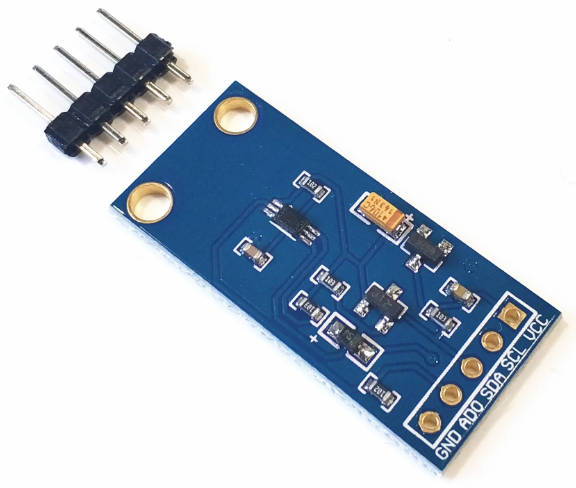
BH1750 light sensor
The BH1750 is a light sensor that directly outputs illuminance in lux.
It communicates via I²C interface, making it compatible with many microcontrollers. With a wide range and high precision, it's commonly used in lighting control, mobile phones, and weather stations to measure environmental light levels.
| Property | Description |
|---|---|
| Disabled | To disable or enable this block. |
| Name | The name of this block. |
| I2C bus | |
| Comment | To optionally enter a comment. It does not impact the generated firmware. |
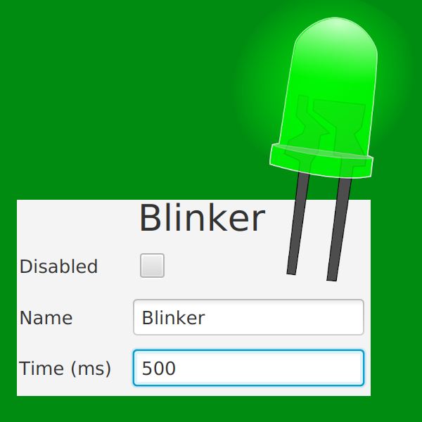
Blinker
See also: Example: Blinking LED
The primary function of the Blinker block is to control the timing of on-off cycles. It can be programmed to switch any compatible device on and off at specified intervals, measured in milliseconds.
When the time is 500 milliseconds, the blinker blinks once per second. 500ms on and 500ms off.
| Property | Description |
|---|---|
| Disabled | To disable or enable this block. |
| Name | The name of this block. |
| Time (ms) | Interval in milliseconds. Smaller time intervals result in faster blinking. Minimum value: 5 ms. |
| Comment | To optionally enter a comment. It does not impact the generated firmware. |
Data transmission
You configure Telecommand & Telemetry here.
See how all this works together in Telemetry.
Deadband
Deadband is a concept referring to a range of input values that do not produce any change in the output. Deadband is used to prevent system instability or unnecessary frequent oscillations, such as a thermostat not turning a heater on and off for minor temperature fluctuations.
Example:
A thermostat is set to maintain the room temperature at 20 degrees Celsius.
To avoid the heater turning on or off for every tiny temperature change,
it can be given a deadband of, for example, 1 degree.
That way, a temperature drop to 19.9 degrees will not turn on the heater,
but a temperature drop to 19.0 or lower will.
| Property | Description |
|---|---|
| Disabled | To disable or enable this block. |
| Name | The name of this block. |
| Input | Input variable |
| Setpoint | Can be a variable or a number |
| Threshold | Width of the range. Example: Setpoint 0, Threshold 1: No output between -1 and 1 (inclusive). |
| Type | |
| Comment | To optionally enter a comment. It does not impact the generated firmware. |
Debounce
To de-bounce an input source, like a switch or a pushbutton.
To make sure a switch connection or button push registers only once it's firmly made.
The debounce functionality is already included in the Debounced Switch block.
| Property | Description |
|---|---|
| Disabled | To disable or enable this block. |
| Name | The name of this block. |
| Source | The source (switch, key, sensor) to de-bounce |
| Comment | To optionally enter a comment. It does not impact the generated firmware. |
Debounced Switch
Hardware switch to ground, with cpu internal pull-up. Software debounced. (1=switch pressed).
Digital input is commonly used to detect the state of switches and buttons. This block also includes the debouncing (See also: Debounce) of the switch or button.
See also: Example: A simple switch and LED.
| Property | Description |
|---|---|
| Disabled | To disable or enable this block. |
| Name | The name of this block. |
| Invert | Invert the output |
| Pin | Pin number. |
| Comment | To optionally enter a comment. It does not impact the generated firmware. |
Derived variable
No info available, yet.
| Property | Description |
|---|---|
| Disabled | To disable or enable this block. |
| Name | The name of this block. |
| Expression | Expression variable |
| Type | Type of variable |
| Comment | To optionally enter a comment. It does not impact the generated firmware. |
Digital input
A single input pin on the CPU.
It can have an optional pull-up.
The naming is dependent on the processor or platform.
For instance, on Arduino it looks like: "D2".
| Property | Description |
|---|---|
| Disabled | To disable or enable this block. |
| Name | The name of this block. |
| Pin | Pin number |
| Pull-up | Check this box to enable the internal pull-up. |
| Comment | To optionally enter a comment. It does not impact the generated firmware. |
Digital output
A single output pin on the CPU.
| Property | Description |
|---|---|
| Disabled | To disable or enable this block. |
| Name | The name of this block. |
| Pin | Output pin number. |
| Source | A source that provides input for this block. |
| Comment | To optionally enter a comment. It does not impact the generated firmware. |
ESP tool override
To override the system defaults with a specific ESP-tool command line.
When you want to use your own ESP-tool-like tool.
| Property | Description |
|---|---|
| Disabled | To disable or enable this block. |
| Command | The command for programming the target. Leave empty for default. |
| Parameters | Leave empty for default |
| Comment | To optionally enter a comment. It does not impact the generated firmware. |
ESP32-S3
The ESP32-S3 processor.
See also: ESP32-S3 Implementation notes
| Property | Description |
|---|---|
| Disabled | To disable or enable this block. |
| Name | The name of this block. |
| Comment | To optionally enter a comment. It does not impact the generated firmware. |
GY-30 light sensor
The GY-30, is a module with the BH1750. It is a digital ambient light sensor that provides precise light intensity measurements.
Operating via the I²C interface, it's often integrated into electronics projects, enabling devices to respond to changing light conditions.
| Property | Description |
|---|---|
| Disabled | To disable or enable this block. |
| Name | The name of this block. |
| I2C bus | Use when platform has multiple I2C busses. |
| Comment | To optionally enter a comment. It does not impact the generated firmware. |
Global variable
No info available, yet.
| Property | Description |
|---|---|
| Disabled | To disable or enable this block. |
| Name | The name of this block. |
| Initial value | Initial value. Default is 0. |
| Type | Type of the variable |
| Comment | To optionally enter a comment. It does not impact the generated firmware. |
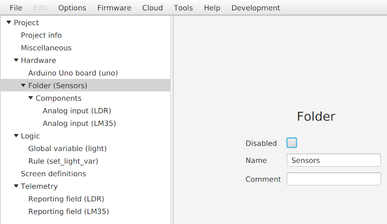
Hardware Folder
A folder can be used to logically group blocks together.
If you disable a folder, all blocks in it are also disabled.
| Property | Description |
|---|---|
| Disabled | To disable or enable this block. |
| Name | A name for the folder. |
| Comment | To optionally enter a comment. It does not impact the generated firmware. |
IDE Preferences
This contains all the settings, private to your IDE. Shared between all the projects you use on this workstation.
Incremental encoder
A block for a incremental encoder.
It exposes a S32 veriable with the name of the block.
If the encoder value increments in the wrong way, swap pin1 and pin2 io pins in hardware or software.
| Property | Description |
|---|---|
| Disabled | To disable or enable this block. |
| Name | The name of this block. |
| Pin1 | The pin with the A-signal. |
| Pin2 | The pin with the B-signal. (90%) |
| Pull-up | Control pullup of both pins. |
| Comment | To optionally enter a comment. It does not impact the generated firmware. |
Indicator
Read about how this works with other screen elements in Screens.
Displays the text belonging to the first expression that is non-zero.
| Property | Description |
|---|---|
| Disabled | To disable or enable this block. |
| Row | Display row, starts at 0 |
| Column | Column, starts at 0 |
| Expression 1 | If this is the first expression evaluated 'true', the corresponding text is displayed |
| Expr. 1 text | Text to display if expression 1 is non-zero |
| Expression 2 | If this is the first expression evaluated 'true', the corresponding text is displayed |
| Expr. 2 text | Text to display if expression 2 is non-zero |
| Expression 3 | If this is the first expression evaluated 'true', the corresponding text is displayed |
| Expr. 3 text | Text to display if expression 3 is non-zero |
| Comment | To optionally enter a comment. It does not impact the generated firmware. |
Keyboard handler
Add this for keyboard.
| Property | Description |
|---|---|
| Disabled | To disable or enable this block. |
| Keyboard variable | Variable that will contain keypresses This can be an expression |
| Comment | To optionally enter a comment. It does not impact the generated firmware. |
LCD Display
For connecting a generic LCD display.
You have to assign the pins to this display component.
- Register Select (0 = command, 1 = data)
- E: Enable
- DB0~DB3: Display data signal; lower byte in 8-bit mode
And the size of the display in rows and columns
- Number of columns
- Number of rows
Next, define what to show in Screens.
| Property | Description |
|---|---|
| Disabled | To disable or enable this block. |
| Name | The name of this block. |
| Rows | Number of rows |
| Columns | Number of columns |
| E | E: Enable |
| RS | Register Select; 0 = command, 1 = data |
| DB0 | DB0~DB3: Display data signal; lower byte in 8-bit mode |
| DB1 | DB0~DB3: Display data signal; lower byte in 8-bit mode |
| DB2 | DB0~DB3: Display data signal; lower byte in 8-bit mode |
| DB3 | DB0~DB3: Display data signal; lower byte in 8-bit mode |
| Comment | To optionally enter a comment. It does not impact the generated firmware. |
LED
A LED connected to a CPU output pin.
An alias for Digital output .
| Property | Description |
|---|---|
| Disabled | To disable or enable this block. |
| Name | The name of this block. |
| Pin | The pin to which the LED is connected. |
| Source | A source that provides input to this LED. For example a blinker. |
| Comment | To optionally enter a comment. It does not impact the generated firmware. |
Logic Folder
A folder can be used to logically group blocks together.
If you disable a folder, all blocks in it are also disabled.
| Property | Description |
|---|---|
| Disabled | To disable or enable this block. |
| Name | A name for the folder. |
| Comment | To optionally enter a comment. It does not impact the generated firmware. |
MQTT
Enable MQTT telemetry.
Is only available on systems with an network connection.
| Property | Description |
|---|---|
| Disabled | To disable or enable this block. |
| Comment | To optionally enter a comment. It does not impact the generated firmware. |
MQTT configuration
To configure the MQTT configuration of the controller direct after programming it.
Example:
mqtt://192.168.1.10
or
mqtts://my.mqtt:1245/
| Property | Description |
|---|---|
| URL | The full url pointing to the MQTT server |
OS ticks
No info available, yet.
| Property | Description |
|---|---|
| Disabled | To disable or enable this block. |
| Name | The name of this block. |
| Comment | To optionally enter a comment. It does not impact the generated firmware. |
Optimizer hints
To set preferences for the optimization by the firmware generator.
| Property | Description |
|---|---|
| Disabled | To disable or enable this block. |
| Optimize for size | |
| Comment | To optionally enter a comment. It does not impact the generated firmware. |
PWM LED
A dimmable LED.
The brightness is specified in percentage. It ranges from 0 (off) to 100 (full on).
See also: Example: Dimmable LED (PWM)
| Property | Description |
|---|---|
| Disabled | To disable or enable this block. |
| Name | The name of this block. |
| Pin | The pin to which the LED is connected. |
| Source | A source (another block) that sets the intensity of this LED, from 0 (off) to 100 (full on). 50=50% brightness. It is also possible to specify a fixed number here. |
| Comment | To optionally enter a comment. It does not impact the generated firmware. |
Page
No info available, yet.
| Property | Description |
|---|---|
| Text | The text to describe this settings page For example: "Set min/max" Maximum length: depends on screen |
Programmer options
Here you configure the target programmer.
The defaults are probably fine, but if you want to use your own programmer program, or use special options, you can configure this here.
Programmer settings
Programmer settings local to this PC.
An menu option for searching the programmer is available for certain programmers.
| Property | Description |
|---|---|
| Port | Which PC port the programmer is connected to |
Project
This represents the top of the project file.
| Property | Description |
|---|---|
| Enable experimental | When enabled allow experimental blocks in project |
Project info
This is only to document your project.
All the fields are for your own administration. They are shown in the generated documentation (if your subscription includes this option).
All fields are optional, you can leave them empty.
| Property | Description |
|---|---|
| Project id | Optional; project identifier It is not included in the generated program |
| Project description | Optional; free text area to describe this project It is not included in the generated program |
| Customer | Optional; customer name It is not included in the generated program |
RGB LED
A RGB LED connected to 3 output pins on the CPU.
Functions the same as 3 PWM LEDs.
Usage
Specify the pins for each colour, and give it a name, for example 'rgb_led'.
Each colour can be set to intensity 0 (off), 25, 50, 75 or 100 (full on), in a logic block.
For example, a logic rule 'set_magenta':
rgb_led.red = 50;
rgb_led.blue = 50;
Because RGB LEDs work with intensity settings from 0 to 100, and Blinker works with on and off only, RGB LEDs can't be used with blinkers.
| Property | Description |
|---|---|
| Disabled | To disable or enable this block. |
| Name | The name of this block. |
| Red | Pin for red LED |
| Green | Pin for green LED |
| Blue | Pin for blue LED |
| Comment | To optionally enter a comment. It does not impact the generated firmware. |
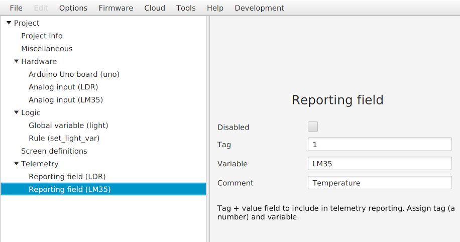
Reporting field
See how all this works together in Telemetry.
| Property | Description |
|---|---|
| Disabled | To disable or enable this block. |
| Variable | The variable to report |
| Tag | A number to identify this variable in the telemetry stream. This number has to be unique. |
| Label | |
| Comment | To optionally enter a comment. It does not impact the generated firmware. |
Rule
A rule is as block of text with a 'C', Javascript like language to describe logic rules.
For more on rules, see: Rules.
| Property | Description |
|---|---|
| Disabled | To disable or enable this block. |
| Name | The name of this block. |
| Script | Logic rule, for example: if ( temp > 25 ) { fan = 1 ; } else { fan = 0 ; } |
| Comment | To optionally enter a comment. It does not impact the generated firmware. |
SP5055
Single chip frequency synthesizer, I2C.
Datasheet SP5050.pdf| Property | Description |
|---|---|
| Disabled | To disable or enable this block. |
| Name | The name of this block. |
| Address | I2C address |
| I2C bus | |
| XTAL frequency | |
| Comment | To optionally enter a comment. It does not impact the generated firmware. |
Schmitt-Trigger
A Schmitt trigger converts varying analogue inputs into binary outputs with defined thresholds.
It provides noise immunity and hysteresis, preventing rapid switching and ensuring stable signal processing.
| Property | Description |
|---|---|
| Disabled | To disable or enable this block. |
| Name | The name of this block. |
| Type | |
| Input | Input variable |
| Lower | Lower threshold; output will be Off if falling edge is below |
| Upper | Upper threshold; output will be On if rising edge is above |
| Off | Desired output value for 'Off' condition |
| On | Desired output value for 'On' condition |
| Comment | To optionally enter a comment. It does not impact the generated firmware. |
Screen Page
A page on a screen.
Read about how this works with other screen elements in Screens.
| Property | Description |
|---|---|
| Disabled | To disable or enable this block. |
| Label | |
| Comment | To optionally enter a comment. It does not impact the generated firmware. |
Serial TLV
Telemetry via a serial connection.
| Property | Description |
|---|---|
| Disabled | To disable or enable this block. |
| Comment | To optionally enter a comment. It does not impact the generated firmware. |
Settings
This is a special screen page definition. It represents a menu driven system for configuring variables within the device.
| Property | Description |
|---|---|
| Disabled | To disable or enable this block. |
| EEPROM magic | M EEPROM |
| Comment | To optionally enter a comment. It does not impact the generated firmware. |
Settings item
Read about how this works with other screen elements in Screens.
| Property | Description |
|---|---|
| Initial value | Initial value, used until this setting has been changed |
| Text | A short indication of this settings item, for example: MaxTemp |
| Type | Type of variable to use |
| Unit | For example: C, F, rpm, mm, inch |
| Variable | Name of the variable to use |
Settings screen
This is a special screen page definition. It represents a menu driven system for configuring variables within the device.
Read about how this works with other screen elements in Screens.
| Property | Description |
|---|---|
| Disabled | To disable or enable this block. |
| Label | |
| Comment | To optionally enter a comment. It does not impact the generated firmware. |
Startup banner
No info available, yet.
| Property | Description |
|---|---|
| Disabled | To disable or enable this block. |
| Line 1 | Text to display: line 1 |
| Line 2 | Text to display: line 2 |
| Time (ms) | Time to show banner (milliseconds) |
| Comment | To optionally enter a comment. It does not impact the generated firmware. |
System activity LED
This represents a GPIO port thats active when tasks in the system are active.
You can connect a LED of oscilloscope to it.
The brightness is a measure of how heavy the system is loaded with aperiodic tasks. The more dimmer, the more energy is saved.
| Property | Description |
|---|---|
| Disabled | To disable or enable this block. |
| Pin | The pin to which the LED is connected. |
| Comment | To optionally enter a comment. It does not impact the generated firmware. |
System tick activity LED
This represents a GPIO port thats active when the tick processing is active.
You can connect a LED of oscilloscope to it.
Normally this is 1000hz.
The brightness is a measure of the load the tick processing causes. The more dimmer, the more energy is saved.
With an oscilliscope you can measure how heavy the CPU is loaded.
It should never be anything near 100% pulsewidth. High values are an indication the solution you have built is too heavy for this CPU.
| Property | Description |
|---|---|
| Disabled | To disable or enable this block. |
| Pin | The pin to which the LED is connected. |
| Comment | To optionally enter a comment. It does not impact the generated firmware. |
Telemetry var mapping
See how all this works together in Telemetry.
Telemetry var wildcard
See how all this works together in Telemetry.
| Property | Description |
|---|---|
| Disabled | To disable or enable this block. |
| Comment | To optionally enter a comment. It does not impact the generated firmware. |
Text field
Read about how this works with other screen elements in Screens.
| Property | Description |
|---|---|
| Disabled | To disable or enable this block. |
| Text | Text to show |
| Row | Row to place the text on Rows start at 0 |
| Column | Column to start the text on Columns start at 0 |
| Comment | To optionally enter a comment. It does not impact the generated firmware. |
Timer
No info available, yet.
| Property | Description |
|---|---|
| Disabled | To disable or enable this block. |
| Name | The name of this block. |
| Script | Script to run when timer expires. |
| Autostart | Timer starts automatically. |
| One-shot | Timer runs only once. |
| Interval | Timer interval in milliseconds. |
| Comment | To optionally enter a comment. It does not impact the generated firmware. |
Variable and label
Read about how this works with other screen elements in Screens.
| Property | Description |
|---|---|
| Disabled | To disable or enable this block. |
| Text | Text to display in front of the variable |
| Variable | Variable to display value of |
| Row | Display row, starts at 0 |
| Column | Column, starts at 0 |
| Length | Total maximum length of text and variable combined |
| Comment | To optionally enter a comment. It does not impact the generated firmware. |
Variable field
Read about how this works with other screen elements in Screens.
| Property | Description |
|---|---|
| Disabled | To disable or enable this block. |
| Variable | Variable to display |
| Row | Row, starts at 0 |
| Column | Column, starts at 0 |
| Length | The maximum number of positions to be used |
| Comment | To optionally enter a comment. It does not impact the generated firmware. |
Wifi configuration
To configure the Wifi configuration of the controller direct after programming it.
| Property | Description |
|---|---|
| SSID | The name of the access point |
| Password | The password of the access point |
Topics
Block name
Most blocks have a name. Usually this forms the base of variable names exposed with the block.
For example a sensor measuring temperature and light, with a name 'sensor' the variables exposed would be 'sensor.light' and 'sensor.temp'.
Disable
With disable you can (temporary) exclude a block.
This allows you to quickly exclude parts of the program, for example when testing incomplete hardware.
Also when a folder is disabled, all the blocks inside this folder are also excluded.
Expressions
See: Rules reference.
Free to use fields
There are some fields for your own use.
It has no effect on the generated firmware.
These can be used in documentation, or to make note of important things.
Like:
- Comment
- Project id
- Customer name
Pin
A pin is a pin on the controller/cpu.
Also known as GPIO (General Purpose IO).
The names follow a platform specific convention.
Arduino platform
For Arduino platform it looks like:
A8 = Analog port 8
D2 = Digital port 2
You can also use AVR8 notation, when the Arduino has a AVR8 cpu.
AVR8 platform
For AVR8 platform it looks like:
PD0 = Pin 0 on port D.
PB2 = Pin 2 on port B.
Rules
A rule is as block of text with a 'C', Javascript like language to describe logic rules.
See also: Rules reference.
Example:
if ( temp > 25  ) {
    fan = 1 ;
} else {
    fan = 0 ;
}
Screens
Screens is a way to define your screens.
Screens are presented as pages.
Changing pages can be by user control, or program control, or both.
Only 1 page at a time is shown.
Screen page
A normal screenpage consists of labels and fields.
Labels are fixed texts
Fields are dynamic texts, presenting values from variables.
A screenpage is divided in a grid. The origin of the grid is top-left. The grid starts counting with 0,0.
Settings page
Settings is a specialized predefined page to edit settings.
Telemetry
Telemetry is the process of transmitting data from a device to a remote system for monitoring and analysis.
This is useful for monitoring, saving sensor values in a database, make graphs, and many more applications.
Telemetry routing
Here you specify which transport to use for the telemetry.
- Serial
- MQTT
To check if available on your target platform, see: Implementation notes
Telemetry var mapping
This is the folder containing the "Reporting field" items. These specify which variable to send.
Reporting field
To add a value to the data stream, enter the name of the variable (this can be a sensor that you have defined in the Hardware folder) and the tag that you want to assign to it.
The tag is a numeric value, you choose, to give an unique id to the value in the case when the transport mechanism is not able to send texts.
Types
| Type | Description | Minimum Value | Maximum Value |
|---|---|---|---|
| BIT | BIT is a 1 bit number. | 0 | 1 |
| U8 | U8 is an unsigned 8-bit integer. | 0 | 255 |
| U16 | U16 is an unsigned 16-bit integer. | 0 | 65,535 |
| U32 | U32 is an unsigned 32-bit integer. | 0 | 4,294,967,295 |
| U64 | U64 is an unsigned 64-bit integer. | 0 | 18,446,744,073,709,551,615 |
| S8 | S8 is a signed 8-bit integer. | -128 | 127 |
| S16 | S16 is a signed 16-bit integer. | -32,768 | 32,767 |
| S32 | S32 is a signed 32-bit integer. | -2,147,483,648 | 2,147,483,647 |
| S64 | S64 is a signed 64-bit integer. | -9,223,372,036,854,775,808 | 9,223,372,036,854,775,807 |
| F16 | F16 is a 16-bit floating point number. | Implementation-dependent | Implementation-dependent |
Each of these data types serves a specific purpose and can be used to optimize memory usage and computational performance in your system.
Bits
A BIT represents a binary digit, which is the smallest unit of data in a computer system. It can hold one of two values.
Integer
"Signed" means it can represent both positive and negative values.
"Unsigned" means it can only represent non-negative whole numbers.
Floating
Floating point numbers are designed to represent real numbers, allowing for a wide range of values with varying degrees of precision. The range and precision of these numbers depends on the specific implementation.
See also: The use of Floating-Point Values in Embedded Applications.
Misc documents
9-in-1 Sensor Shield
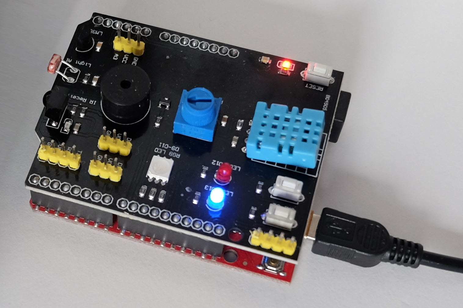
The 9-in-1 Sensor Shield is a multifunctional module designed for easy interfacing with various sensors. It enables rapid prototyping by providing a streamlined interface for multiple input and output devices. Key features include temperature, humidity, light, sound, and motion sensors, among others. Ideal for Arduino-based DIY projects and education.
Pinning
| Inputs & outputs | Arduino pin # | Remarks |
|---|---|---|
| LED 1 (blue) | Digital pin 12 | |
| LED 2 (red) | Digital pin 13 | |
| Switch 1 | Digital pin 2 | |
| Switch 2 | Digital pin 3 | |
| DHT11 | Digital pin 4 | Temperature & humidity sensor (not implemented for Arduino and AVR8 platforms) |
| Buzzer | Digital pin 5 | |
| Infrared receiver | Digital pin 6 | |
| RGB LED | Digital pins 9-11 | red D9, blue D10, green D11 |
| Potentiometer | Analog pin 0 | |
| LDR | Analog pin 1 | Light dependent resistor |
| LM35 | Analog pin 2 | Temperature sensor |
Arduino Mega implementation notes
See also:
Pin naming
You can use the Arduino's convention for naming IO ports, such as 'A1' for analog pins and 'D20' for digital pins. It starts counting with A0 and D0.
Telemetry
There is only serial telemetry available because of lacking internet supporting hardware.
Arduino Uno implementation notes
See also:
Pin naming
You can use the Arduino's convention for naming IO ports, such as 'A1' for analog pins and 'D20' for digital pins. It starts counting with A0 and D0.
Telemetry
There is only serial telemetry available because of lacking internet supporting hardware.
Block name
Most blocks have a name. Usually this forms the base of variable names exposed with the block.
For example a sensor measuring temperature and light, with a name 'sensor' the variables exposed would be 'sensor.light' and 'sensor.temp'.
Condition examples
Testing for a condition
Equals
if( a == 10 ) { q = 1 ; }
Not equal
if( a != 10 ) { q = 1 ; }
Greater than
if( a > 10 ) { q = 1 ; }
Greater than or equal
if( a >= 10 ) { q = 1 ; }
Less than
if( a < 10 ) { q = 1 ; }
Less than or equal
if( a <= 10 ) { q = 1 ; }
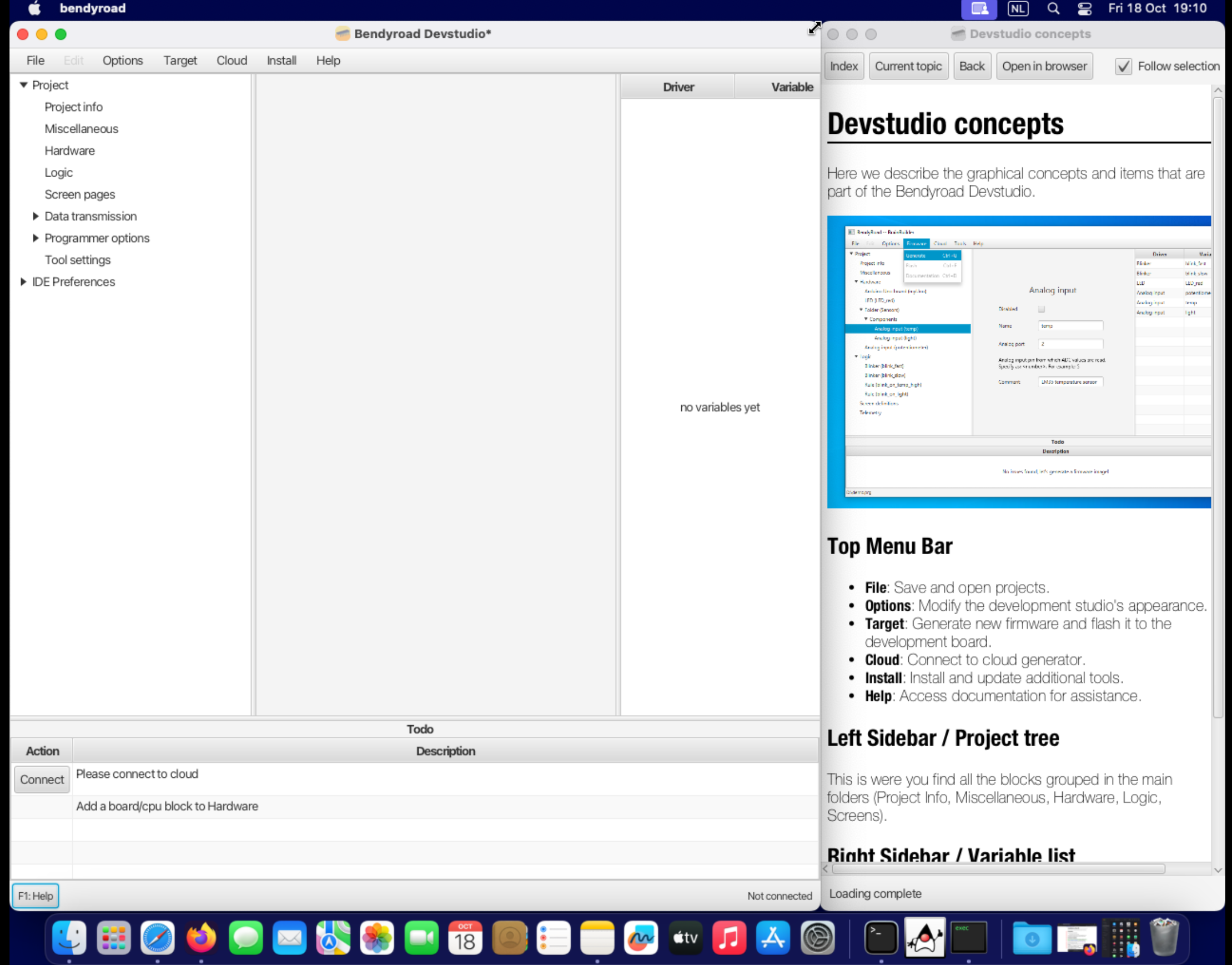
Devstudio concepts
Here we describe the graphical concepts and items that are part of the Bendyroad Devstudio.
Top Menu Bar
- File: Save and open projects.
- Options: Modify the development studio's appearance.
- Target: Generate new firmware and flash it to the development board.
- Cloud: Connect to cloud generator.
- Install: Install and update additional tools.
- Help: Access documentation for assistance.
Left Sidebar / Project tree
This is were you find all the blocks grouped in the main folders (Project Info, Miscellaneous, Hardware, Logic, Screens).
Right Sidebar / Variable list
Here you'll find a list of variables for easy reference. It is maintained automatically.
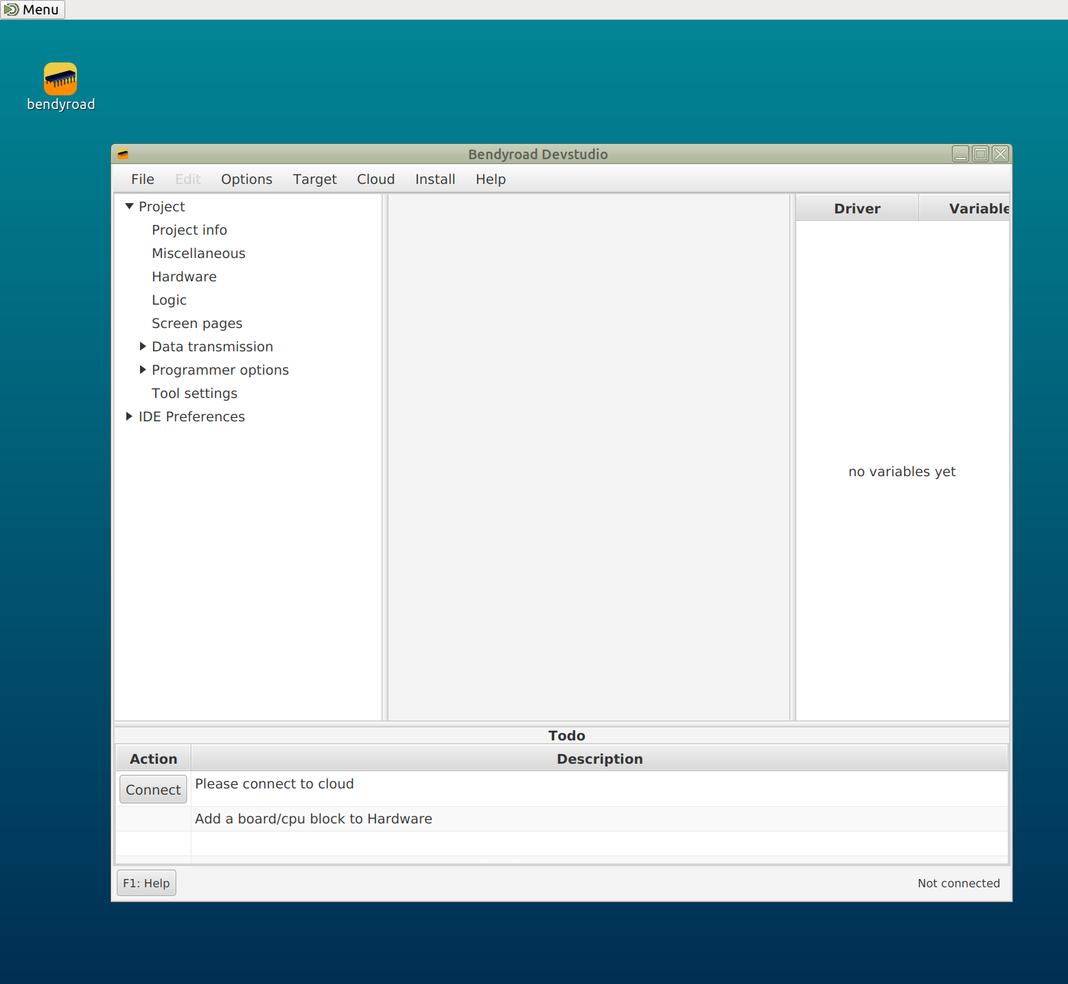
ToDo info area
This lists the next actions to do. For example when starting a new project, the first thing to do is adding a development board. This will be shown here as a 'to do' item.
Disable
With disable you can (temporary) exclude a block.
This allows you to quickly exclude parts of the program, for example when testing incomplete hardware.
Also when a folder is disabled, all the blocks inside this folder are also excluded.
ESP32-S3 Implementation notes
See also:
Disabled ADC2
The ESP32-S3 Errata sheet provides a warning against the use of the ADC2. Due to this warning, we have decided to exclude the use of the ADC2 in our implementation.
For more detailed information, you can refer to the official ESP32-S3 Errata sheet
Currently implemented
- GPIO
- TWI
- ADC
- MQTT
- WIFI
Example: A simple switch and LED
- the switch has the 'name': 'sw1'
- and connected to 'port' 'D11' (or any other port you chose)
- use the current value of 'sw1' in a rule, for example
set a LED on when sw1 is on:
if ( sw1 ) {
    led1 = 1 ;
} else {
    led1 = 0 ;
}
Example: Air quality alerting with a MQ135 sensor
The MQ-135 sensor detects harmful gases in the air, such aas NH3, NOx, alcohol, and benzene.
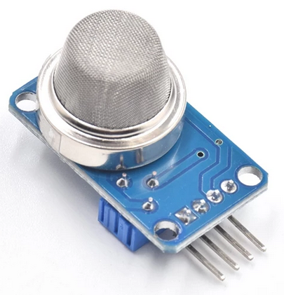
The sensing element reacts to concentrations of certain gases by changing its resistance.
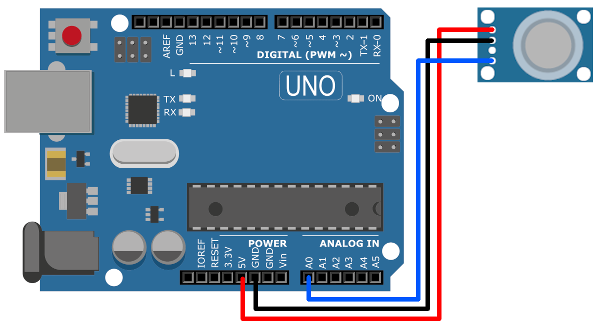
Hardware setup
To wire the gas sensor up to an Arduino, connect the VCC and GND appropriately, and the signal wire to an analog pin, in this example pin 0.
Making the firmware
In this example, we're using a threshold value of '200'. When the sensed value is greater than that, the on-board LED is turned on.
Instead of turning on a LED, you can sound a buzzer or start a fan motor.
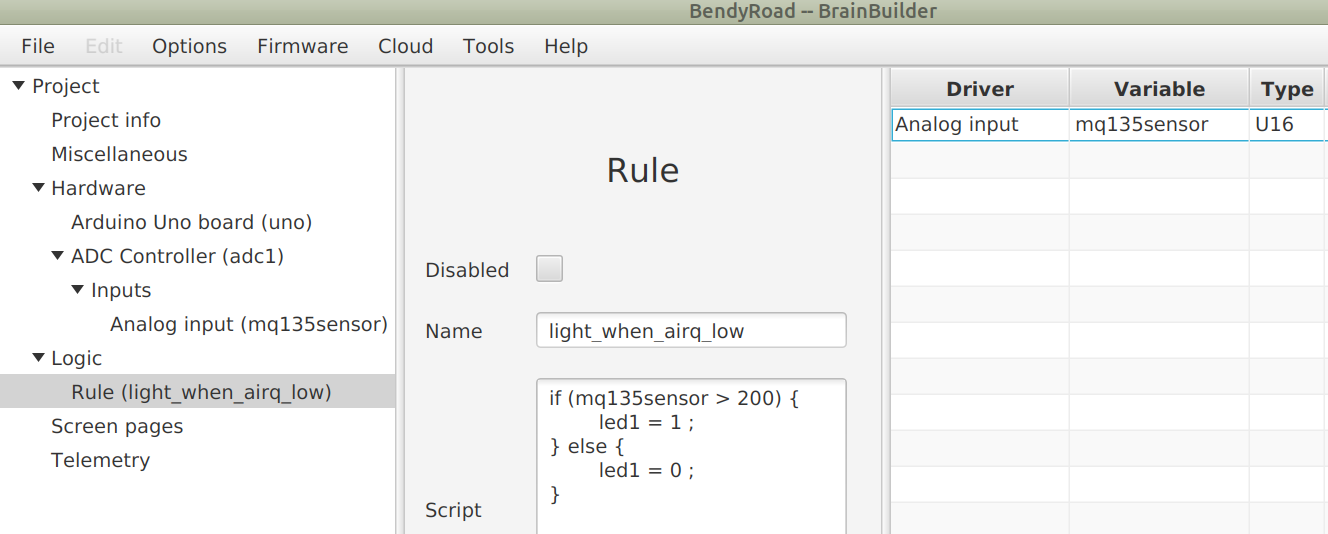
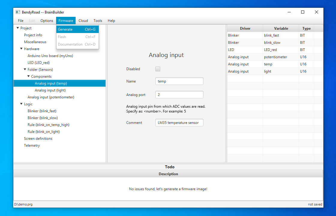
This screenprint shows all there is to it: a sensor defined, and a basic logic rule to switch the LED on or off depending on the sensor value.
MQ gas sensors have a heating element and need approx. 180 mA to power the heating element, so you can't power a lot of them from one microcontroller.
Example: Ambiant temperature measurement with a TMP36 sensor
Introducing the TMP36 sensor, a versatile analog device renowned for its linear temperature-to-voltage output. This guide offers a step-by-step approach on interfacing the sensor with an Arduino, processing its readings, and implementing logic based on the derived temperature.
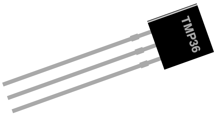
The TMP36 sensor (and TMP35 and TMP37) provide a voltage output that is linearly proportional to the temperature in Celsius.
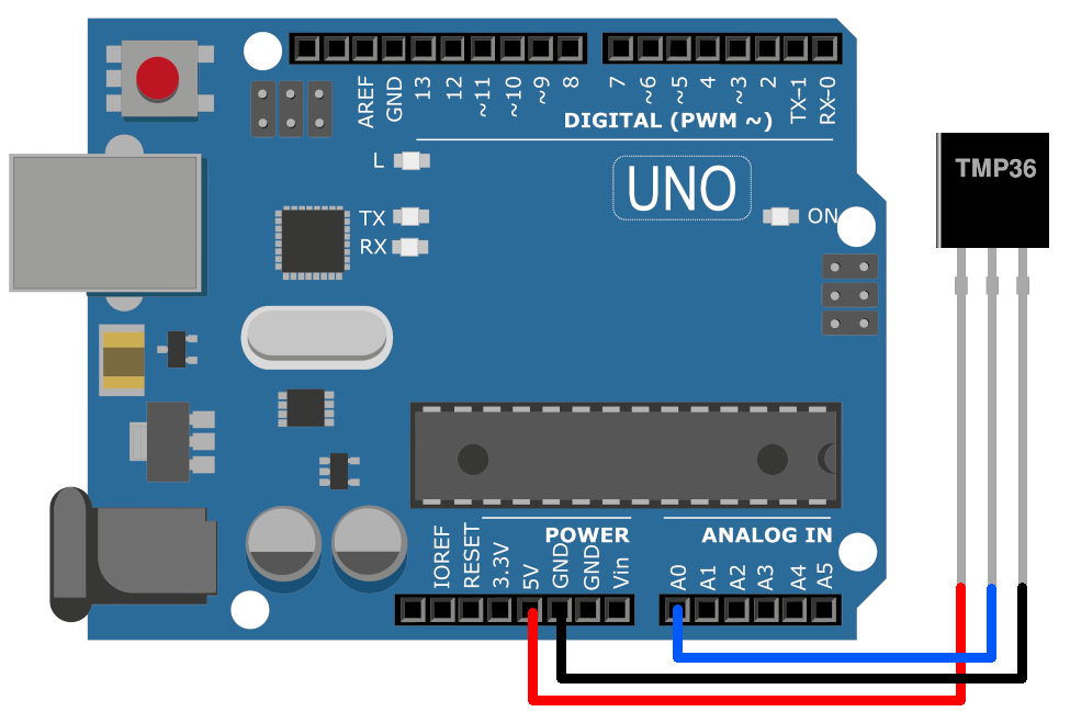
Hardware setup
To wire the temperature sensor up to an Arduino, connect the VCC and GND appropriately, and the signal wire to an analog pin, in this example pin 0. In this picture, the flat part of the package is shown in front. Make sure what the pinout is of the sensor you are using, by checking the documentation that belongs to it.
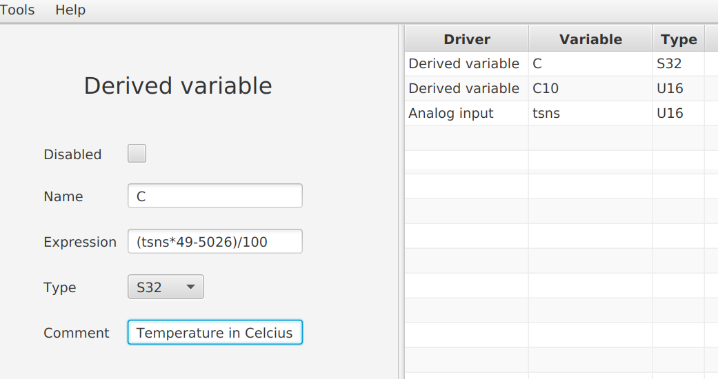
Making the firmware
To illustrate the use of the concept of [[Variables|Derived variables]], we're calculating the temperature in degrees Celcius.
For more information on this calculation, see: Temperature sensors TMP35, TMP36 and TMP37.
Next, a rule is used: when the temperature is higher than 18 C, the on-board LED is turned on. Surely you'll want to do something more useful, for example turning on the heating, the LED is just to illustrate the idea.
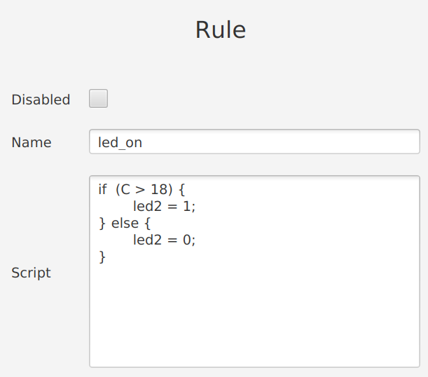
That's all there is to it: a sensor, calculating the temperature, and basic logic rule to switch the LED on or off depending on the temperature.
It becomes a lot more interesting once you start using Settings to change the temperature setting using a Arduino LCD Keypad Shield and Keyboard handler.
Example: Blinking LED
Download program: blink.prg
This program consists of a blinker to drive the blinking cycle. Followed by a logic rule to connect the blinker value to the led. The led is included on the Arduino board.
The blinker time parameter is the time the blinker value is '1'. So 500ms gives a blink cycle with 500ms on, and 500ms off.
Example: Dimmable LED (PWM)
Is in preparation.
Expressions
See: Rules reference.
Free to use fields
There are some fields for your own use.
It has no effect on the generated firmware.
These can be used in documentation, or to make note of important things.
Like:
- Comment
- Project id
- Customer name
Getting started
Installing Bendyroad Development Studio
If you haven't installed yet, go to: Installation.
Starting the Development Studio
Double-click the desktop icon for the Bendyroad Devstudio.
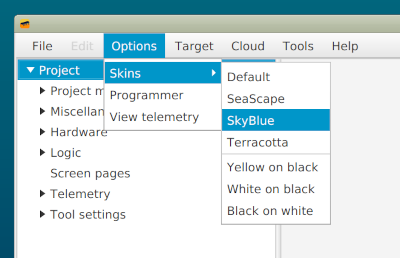
On first startup, you may find it a little too grayish, so you can choose a different skin:
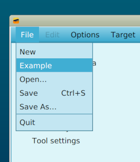
Exploring the built-in example
Under 'File', 'Example' is the classic "hello world" of firmware: the blinking LED.
Connecting a development board
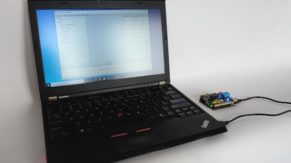
The example is for the Arduino Uno, but it is easily changed for other development boards. More on that later.
Go to 'Target', then 'Search programmer' to start the autoscan for a development board. Sometimes it can take a while to try a few ports before the board is found. (Only one connected board at the same time is supported)
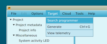
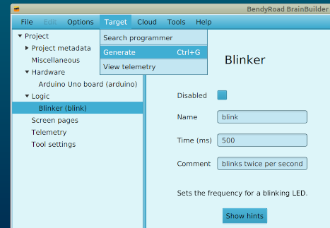
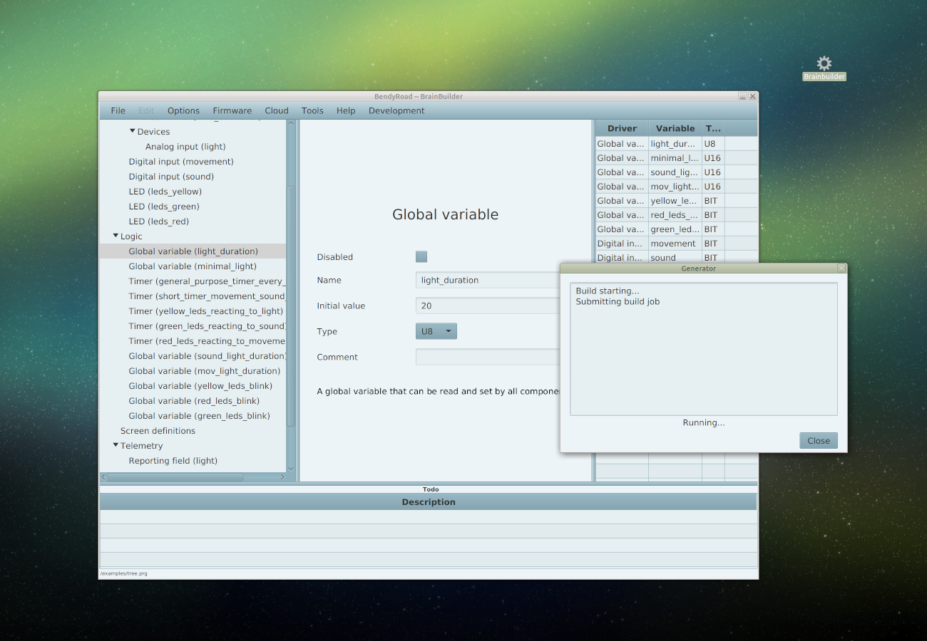
Generating the firmware
Go to 'Target', then 'Generate' to generate the example
The first time you use Bendyroad Devstudio, a browser window will open to link your workstation.
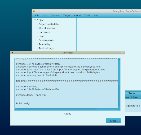
Once the workstation is linked, the firmware is generated. Linking is a one-time thing, so the next times you generate firmware, it will be immediate.
After a few seconds the firmware is generated, flashed, and running on the development board.
Changing the example
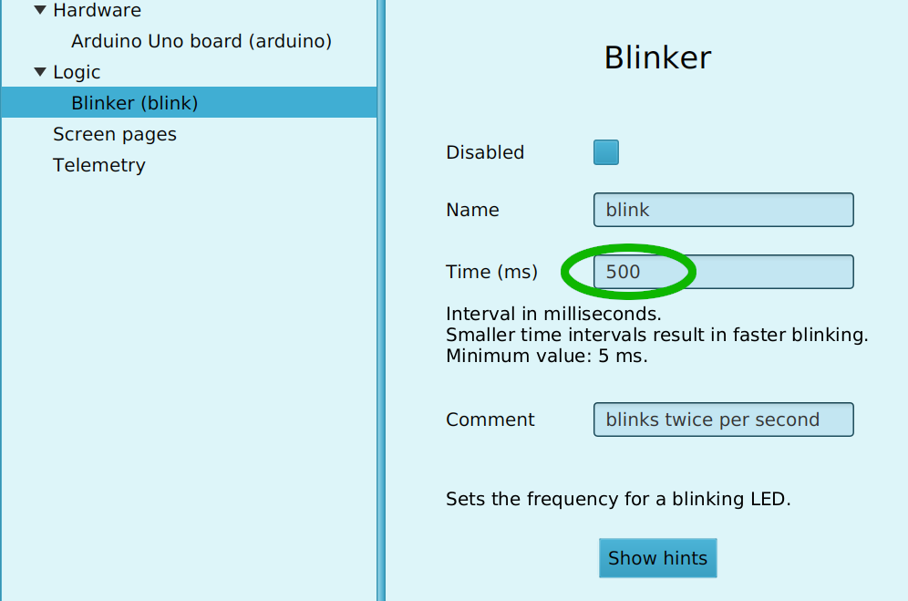
It's a good start to change the frequency of the 'blink', generate again, and see your change become effective quickly.
Saving the project file
It's convenient to create a folder to store your projects in. The folder is remembered for the next times you start Bendyroad Devstudio.
Starting a new project
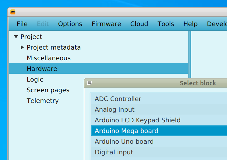
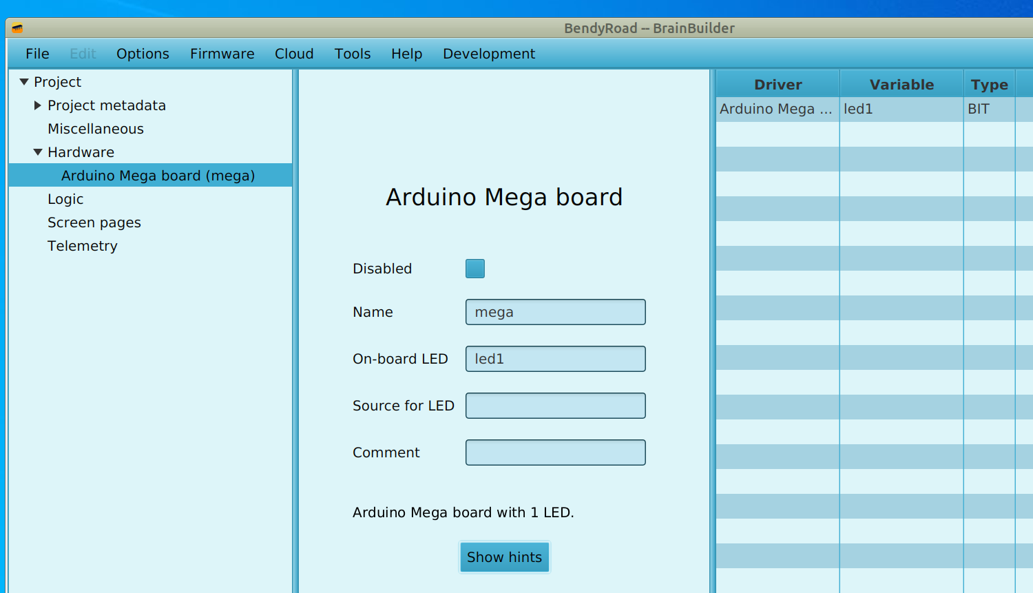
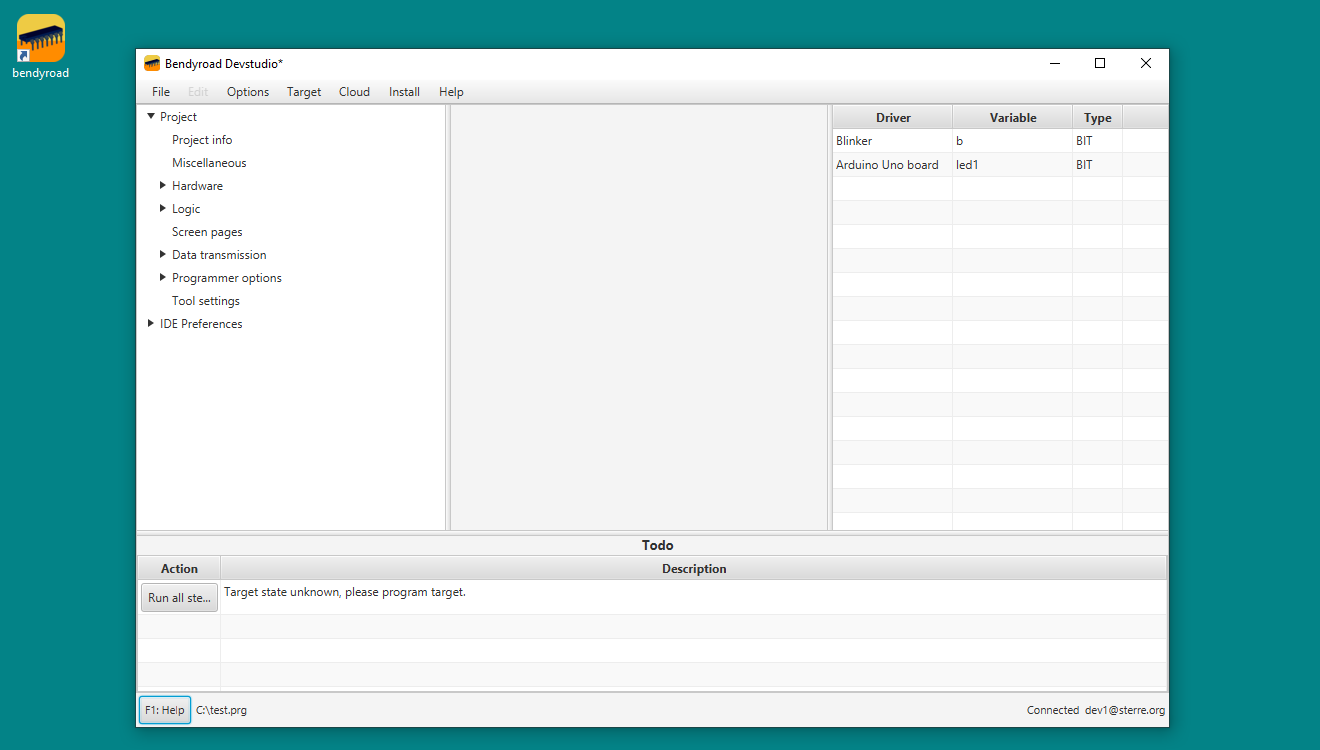
When starting a new project from scratch, always start by adding a development board (left-click on the 'Hardware' folder). For example an Arduino Mega board.
You can change the automatically assigned name to a name that is meaningful to you. The on-board LED is also assigned a default name that you can change. Note that in the list of variables on the left, 'led1' has been added as a variable of type 'bit'.
Adding more hardware
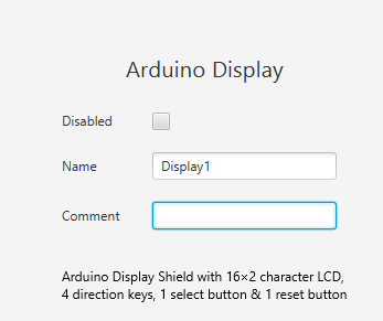
Display
If you have a Arduino Display shield or a generic LCD Display, you can add that too in the same way.
LEDs
Arduino Uno and Mega have an on-board LED that is already configured and available as 'led1'. Other LEDs you can add yourself.
Input
With analog and digital inputs, you can define which sensors or switches are connected to which pins.
Example: For using an analog temperature sensor on analog input pin 2, use an Analog Input block, name it 'temp' and specify the port as '2'.
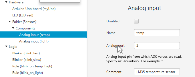
By clicking on any of the field descriptions, help texts are displayed, as in this example by clicking on 'Analog port'.
This automatically adds the variable temp. The list of variables on the right-hand side of the screen is updated with the new variable.
Output
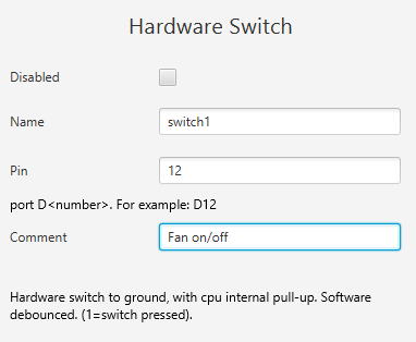
Example: A switch connected to Digital Output port 'D12'
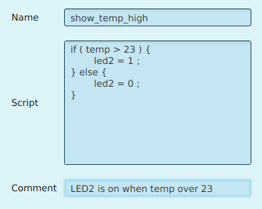
Logic
Rule blocks specify actions based on conditions. For example, to switch 'led2' on when 'temp' level over 23, and off if is below, add a rule like this:
if ( temp > 23 ) {
    led2 = 1;
} else {
    led2 = 0 ;
}
Global variables
Input blocks implicitly make variables available with the name of that block. For example 'Light'. But if it is easier to work with the inverse value, we can define a Global Variable with the name 'LightInverted' and type U16. Then we can add a Rule Block to set the variable 'LightInverted' to '1024 - Light'.
Output
If you have a LCD connected to your Arduino, add it as a hardware item:
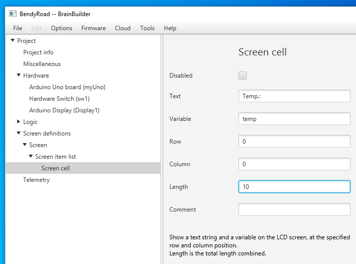
Next, add a 'Screen' under 'Screen Definitions'. This will create a 'Screen Item List', to which you can add 'Screen cells'.
A screen cell is the easiest way to display a text and a value together.
For example, to show the ADC value from the temperature sensor on the display, specify text 'Temp.: ', and a value from a temperature sensor (temp).
The Arduino display has two rows of 16 characters. Numbering starts at 0. An easy way to get the lay-out correct is to use grid paper.
You can enter project information on the Project Info page. There's room for a description and notes.
Reordering blocks
You can drag and drop blocks to reorder them, and organize them in folders, to logically group blocks together.
Glossary
Term:
Target
Definition:
A "target" refers to the specific hardware platform or device that the embedded software is designed to run on. This includes arduino, microcontrollers, microprocessors, or any other type of embedded system.
Installation
Installation on Linux with snap
Installation on Debian/Ubuntu
Steps to get ready to run Bendyroad Development Studio for the first time:
Prerequisites
Check the minimum system requirements:
- Ubuntu 20.04 (Focal Fossa) (or newer), Debian Stable/Buster/10.9
- Display size 1024 x 768
- All security updates installed
You may be able to use other versions, but we do not test these. If you run into problems when using other versions, you have to fix them yourself.
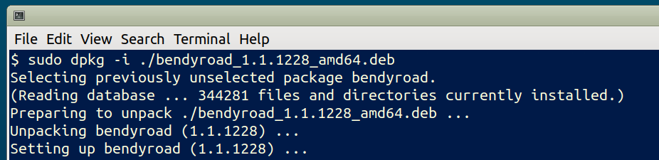
Install Bendyroad Devstudio
Download the Bendyroad Development Studio Linux installer package.
Install the package:
sudo dpkg -i ./bendyroad_[version]_amd64.deb
Check group membership for accessing your development board
Connect your development board
Look up by which group it is owned:
ls -l /dev/tty*
The one to look out for will be named /dev/ttyUSB[number] or /dev/ttyACM[number], for example:
crw-rw----+ 1 root dialout 188, 0 nov 9 10:05 /dev/ttyUSB0
Usually the group it belongs to, is group 'dialout'. Check if you are a member:
groups
Add yourself to the 'dialout' group if you are not a member:
sudo usermod -a -G dialout [your user name]
Start the Bendyroad Development Studio
Start the Devstudio from the menu (Programming):
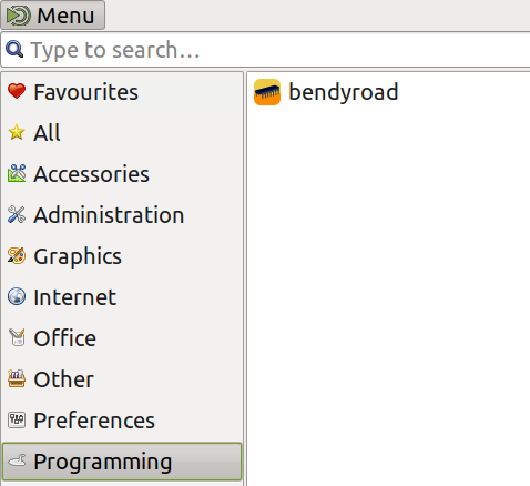
Or create a desktop shortcut for:
/opt/bendyroad/bin/bendyroad
Or start the Devstudio from a terminal window, add /opt/brainbuilder/bin/ to PATH, whichever you prefer
Start creating!
- Connect your development board
- Continue to Getting started
Installation on Linux with snap
Click on [Get it from the Snap Store] in the above image, and follow the instructions.
Access to USB devices
Don't forget to enable access to USB ports when you want to make use of USB based MCUs.
sudo snap connect bendyroad:raw-usb
Menu entry
A menu entry for Bendyroad Devstudio will be created in the "Other" category.
Start creating!
- Connect your development board
- Continue to Getting started
Installation on Mac OS
Steps to get ready to run Bendyroad Development Studio for the first time:
Prerequisites
Check minimum system requirements:
- macOS Catalina / Ventura (Intel-based)
You may be able to use other versions, but we do not test these. If you run into problems when using other versions, you have to fix them yourself.
Download & Installation
If you encounter any difficulties during the Windows installation process, refer to Troubleshoot mac installation for troubleshooting assistance.
Download the Bendyroad Development Studio MacOS installer package.
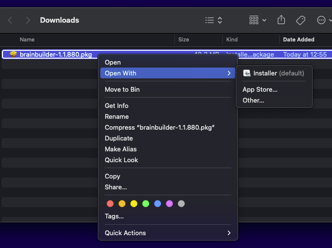
Open the 'Downloads' folder in Finder.
Right-click on bendyroad-[version].pkg, and choose menuitem Open with [Installer].
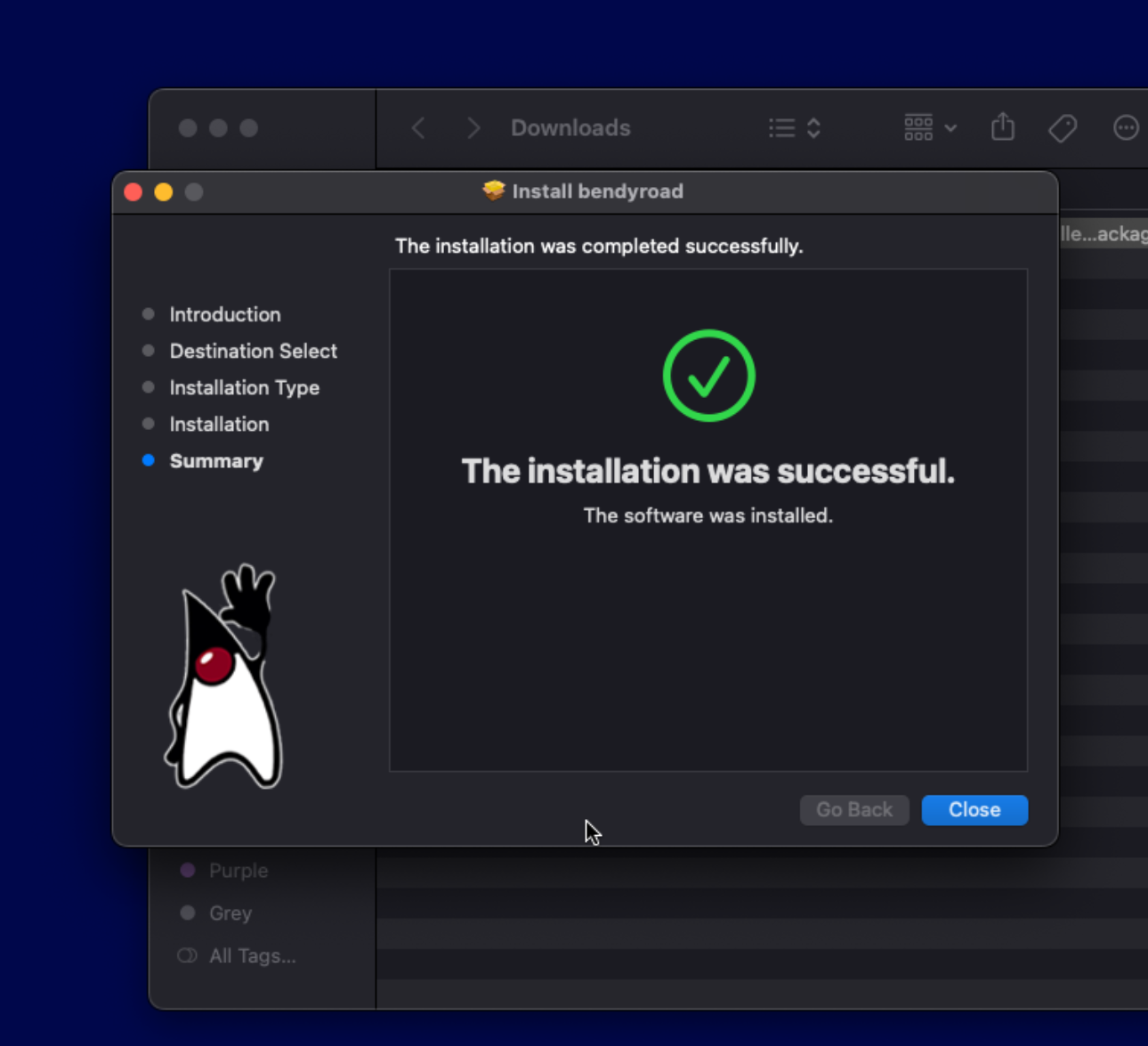
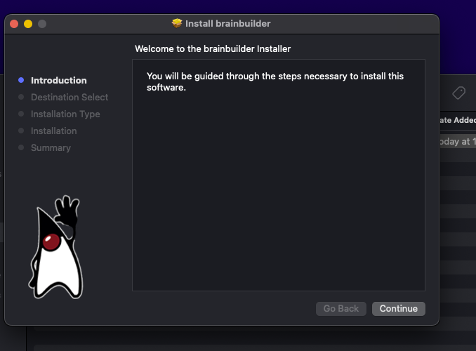
A warning pops up, click [Open]. The installer starts (if nothing seems to happen, it will be behind the Finder window).
After 'The installation was successful', click [Close]. You can now move the installer package to the Trash bin.
Starting the Development Studio
You'll find Bendyroad in the Finder under Applications. Double-click it to start the Development Studio.
Please note that the first time you start Bendyroad Development Studio, it may take a little longer as it downloads the necessary program files.
For a more visually appealing experience, you can choose from various colorful themes by accessing the Options menu and selecting "Skins".
For easy access, you can drag the Bendyroad Devstudio icon from Finder/Applications or from the Launchpad to the Dock.
Start creating!
- Connect your development board
- Continue to Getting started
Installation on Windows
Steps to get ready to run Bendyroad Development Studio for the first time:
Prerequisites
Check minimum system requirements:
- Windows 10 or 11.
- Display size at least 1024 x 768
- All security updates installed
You may be able to use other versions, but we do not test these. If you run into problems when using other versions, you have to fix them yourself.
Download & Installation
If you encounter any difficulties during the Windows installation process, refer to Troubleshoot windows installation for troubleshooting assistance.
To begin the installation process, download the Bendyroad Development Studio Windows installer package and save it.
Once the download is complete, navigate to the Downloads folder and double-click on the downloaded Windows Installer (bendyroad-[version].msi) file to start the installation.
At this point, Windows may display a warning message stating "Windows protected your PC". To proceed, click on [More info].
Next, click on [Run Anyway] to initiate the installer.
You will be prompted to read and accept the terms of the license. Click [Yes, I accept] to proceed.
Once the installation is finished, you will find an icon for Bendyroad on your desktop.
To launch the Development Studio, double-click the Bendyroad icon.
Please note that the first time you start Bendyroad Development Studio, it may take a little longer as it downloads the necessary program files.
For a more colourful experience, you can choose from various themes by accessing the Options menu and selecting "Skins".
Start creating!
- Connect your development board
- Continue to Getting started
Interactive treelights

It's the festive season! So I made this interactive tree to brighten and cheer up to my desk. It senses that I'm there, reacts when I talk to it (I like to think so, but in reality it reacts to any loud enough noise) and switches off when I leave.
There is much more to it than being a pretty ornament: it showcases how Bendyroad supports the use of multiple timers. No less than five independent timers are in use here.
Materials used
- Arduino Mega (or Uno)
- FC-04 sound detector
- Passive infrared sensor HC-SR501
- A light sensor
Light sensor
A GY-30 I2C light sensor module, or an analog light sensor (LDR) works just as well, if using an LDR you'll also need a 10K resistor
For the lights
- 6 LEDs, size 3mm, in 3 colors (colors not a requirement)
- 3 100 Ohm resistors
- wire
- 3 breadboard jumper wires
- heat-shrink tubing
If you are sure you will always use all three LED-strings together, you can connect the three ground wires together. I wasn't sure so I made them suitable for separate use. You may have to tweak the resistor values to get equal amounts of light from the different colour LEDs.
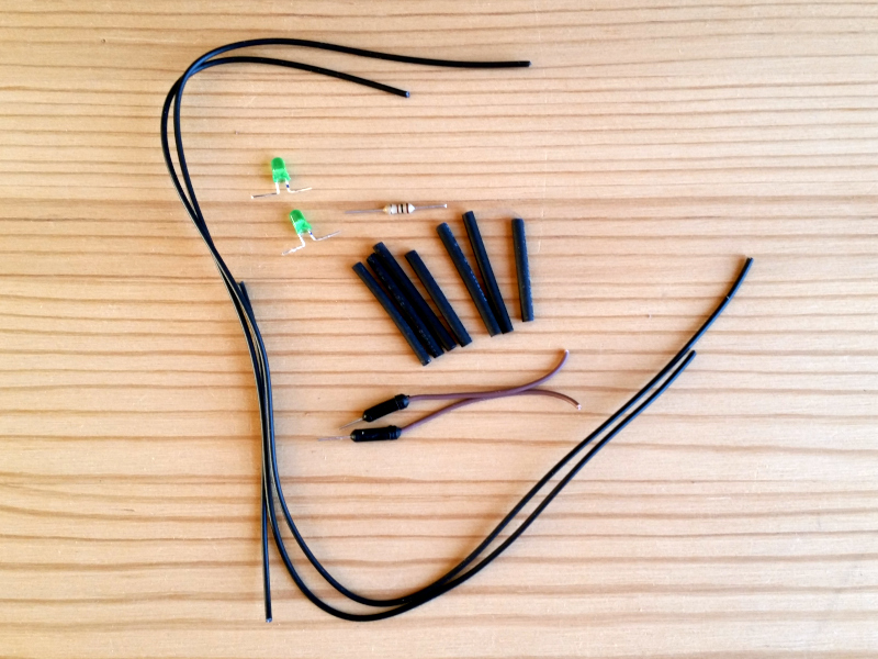
Assembly
First I tested if the LEDs were OK, and if two LEDs in series could be driven from one digital output. Then I marked the long (anode) leads before bending and trimming them. Then prepared 2 long pieces and 1 short piece of wire for each 2-LED 'string'. I sacrificed one breadboard jumper wire to create two plugs on either end of the long wires. Then I put the pieces of heat-shrink tubing in place. Soldered everything together like this:
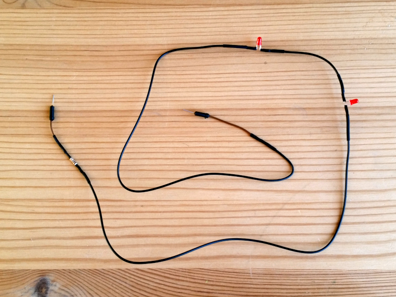
half a jumper wire - resistor - long wire - LED 1 - short wire - LED 2 - long wire - other half of jumper wire
And tested the assembled LED'string', so I was sure it was working before using the hot air on the heat-shrink tubing. I could say the tubing enhances aesthetics, but it's also great to hide soldering work - I need that ;-)
Configuring the tree
Assembling the hardware took the most time, but from here on, you're almost done. Making the firmware with Bendyroad is super quick.
Functions of the firmware
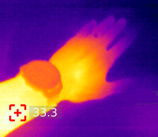
The PIR sensor is triggered by changes in its infrared view of the world. A human is much warmer than the surrounding environment, so whenever I move, the sensor 'sees' it. For more information see: Notes on the HC-SR501 PIR sensor.
The red LEDs blink for a while whenever I move. The sound sensor responds to sound waves (it is a very basic thing, it cannot distinguish frequency, or record speech), but it can detect an increase of noise. When there is enough noise, the green LEDs blink for some time. Whether it's me talking, or enthusiastic co-workers, doesn't matter. And then there is the light sensor, that I set up to enable the blinking yellow LEDs as long as there is ambient light. If it is completely dark, all LEDs are off.
Initially I wanted the LEDs off when it was silent AND dark AND no movement, but that can be annoying and/or provoke undesirable reactions by pets. It is easy enough to change.
Experiment with it
Download the example program: xmastree.prg and save the file 'xmastree.prg' in your Bendyroad Development Studio work directory.
Start the Bendyroad Development Studio and open the example.
Check if the right development board is specified; that's under 'Hardware', default is an Arduino Mega. If you use an Arduino Uno, delete the Arduino Mega (right-click, then delete), and add an Arduino Uno, and give a name to the Mega.
If you want to change any of the default settings or behavior, change them in the Development Studio.
More ideas
- More or other sensors; for example temperature or VOCs (Volatile Organic Compounds, ethanol is one)
- Using RGB LEDs
Notes on the HC-SR501 PIR sensor
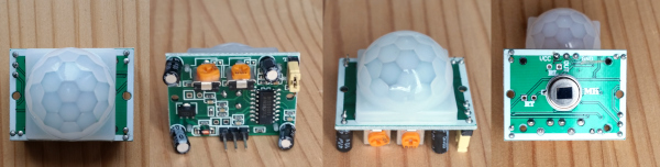
The HC-SR501 is a device that connects to a Bendyroad digital input.
Passive infrared have a very wide field of view and 'see' infrared. In the right-most picture the 'image sensor' is shown. In normal use the image sensor is behind the white plastic 'lens'. They are very good at detecting movement by objects and life forms that are warmer than their surroundings.
If something changes in their view, the output signal is set to 'high'.
Settings
Finding the right settings for the potentiometers may require some experimentation to get them exactly right for your application.
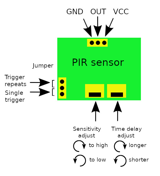
Sensitivity
The sensitivity can be adjusted from 3 meters (potentiometer fully clockwise) to 7 meters (fully counter-clockwise)
Time delay
The time delay can be adjusted from 5 minutes (potentiometer fully clockwise) to 3 seconds (fully counter-clockwise)
Trigger mode
Single-trigger mode ('L'): after motion has been detected, output is set high for the duration of one time delay period only. Repeatable trigger mode ('R'): in addition, motion detected during the time delay period starts the time delay again.
Pin
A pin is a pin on the controller/cpu.
Also known as GPIO (General Purpose IO).
The names follow a platform specific convention.
Arduino platform
For Arduino platform it looks like:
A8 = Analog port 8
D2 = Digital port 2
You can also use AVR8 notation, when the Arduino has a AVR8 cpu.
AVR8 platform
For AVR8 platform it looks like:
PD0 = Pin 0 on port D.
PB2 = Pin 2 on port B.
Rules
A rule is as block of text with a 'C', Javascript like language to describe logic rules.
See also: Rules reference.
Example:
if ( temp > 25  ) {
    fan = 1 ;
} else {
    fan = 0 ;
}
Rules reference
The decision logic is specified in multiple rules.
Rule
A rule consists of a list of one or more statements.
Statement
A statement always ends with a ';' semi-colon. Multiple statements can be combined.
Example:
<statement> ;
<statement> ;
or:
<statement> ; <statement> ;
There are 2 kinds of statements:
- if-statement
- assignment
The 'if' statement
An "if" statement can have the following forms ;
if( <expression> ) { <statements> } else { <statements> };

if( <expression> ) { <statements> } ;
The else part is optional.
If the expression evaluates to non-zero the first statements will be executed.
If the expression evaluates to zero the next list of statements will be executed. The 'else' part of the if statement.
For example:
if( temp > 10 ) {
    fan = 1 ;
} else {
    fan = 0 ;
}
Expression
An expression can be a single item or a combination of expressions.
Constants, for example:
10
12345
Variables, for example:
temp
fan
Operator expressions are formed as:
<expression> <operator> <expression>
For example, arithmetic expressions:
a + z
b / c
d * e
f - g
Boolean expressions:
a < 10
b < c
c > d
e == f
e <= f
e >= f
Assignment
A assignment consists of a left part and a right part combined with an '=' (equal) sign. The left part should always be a variable reference. The right part is an expression.
<variable> = <expression> ;
For example:
temp = temp2 - 10 ;
Screens
Screens is a way to define your screens.
Screens are presented as pages.
Changing pages can be by user control, or program control, or both.
Only 1 page at a time is shown.
Screen page
A normal screenpage consists of labels and fields.
Labels are fixed texts
Fields are dynamic texts, presenting values from variables.
A screenpage is divided in a grid. The origin of the grid is top-left. The grid starts counting with 0,0.
Settings page
Settings is a specialized predefined page to edit settings.
Telemetry
Telemetry is the process of transmitting data from a device to a remote system for monitoring and analysis.
This is useful for monitoring, saving sensor values in a database, make graphs, and many more applications.
Telemetry routing
Here you specify which transport to use for the telemetry.
- Serial
- MQTT
To check if available on your target platform, see: Implementation notes
Telemetry var mapping
This is the folder containing the "Reporting field" items. These specify which variable to send.
Reporting field
To add a value to the data stream, enter the name of the variable (this can be a sensor that you have defined in the Hardware folder) and the tag that you want to assign to it.
The tag is a numeric value, you choose, to give an unique id to the value in the case when the transport mechanism is not able to send texts.
Temperature sensors TMP35, TMP36 and TMP37

The TMP36 (and TMP35 and TMP37) is a low-cost, precision temperature sensor that can be used to measure the temperature of a wide range of objects or environments. They output an analog voltage signal that is proportional to the temperature (in Celsius) being measured. This makes them very easy to work with.
Connect one to an analog input pin (see: Analog input, and the value (between 0 and 1024) read from the pin can be converted to Celcius by this formula:
( ( sensor_value / 1024 * Vcc_in_millivolts) - offset_value_in_millivolts )
/ scaling_factor
Take the offset_value_in_millivolts and scaling_factor from the table below.
| Sensor | Offset voltage (mV) | Scaling (mV/C) | Output at 25C (mV) |
|---|---|---|---|
| TMP35 | 0 | 10 | 250 |
| TMP36 | 500 | 10 | 750 |
| TMP37 | 0 | 20 | 500 |
For example, for a TMP36, 5V Vcc it would be as follows:
( ( sensor_value / 1024 * 5000) - 500 ) / 10
Which can be simplified as:
( sensor_value * 500 / 1024 ) - 50
Or even:
( sensor_value * 49 - 5026 ) / 100
You can check the math using the reference mV at 25C.
The use of Floating-Point Values in Embedded Applications
Recommendation
Be sure to also read the next paragraph when deciding to use floating-point variables and values.
If you decide to use floating-point values in your embedded application, ensure that you understand the implications and potential pitfalls. Consider using fixed-point arithmetic or integer operations wherever possible to maintain accuracy, performance, and reliability. Always test thoroughly in real-world scenarios to ensure system stability and correctness.
WARNING! Dangers ahead!
Precision Limitations
Floating-point numbers have inherent precision limitations. Small rounding errors can accumulate over time, leading to significant inaccuracies in calculations.
Performance Overhead
Floating-point operations, especially on microcontrollers without a dedicated floating-point unit (FPU), can be significantly slower than integer operations. This can lead to performance bottlenecks in time-critical applications.
Memory Consumption
Floating-point variables typically consume more memory than their integer counterparts. This can be a concern in embedded systems with limited memory resources.
Non-deterministic Behavior
Due to the imprecise nature of floating-point arithmetic, results can sometimes be non-deterministic, especially when comparing values for equality.
Complexity in Error Handling
Handling errors or exceptions related to floating-point operations (like underflow, overflow, or division by zero) can add complexity to your code.
Portability Issues
Different microcontrollers or compilers might implement floating-point arithmetic differently, leading to inconsistencies when porting code between platforms.
Power Consumption
Floating-point operations can consume more power, which might be a concern for battery-operated devices.
Limited Support
Some low-end microcontrollers might not support floating-point operations at all, or they might require additional libraries to emulate such operations.
Debugging Challenges
Debugging floating-point issues, especially rounding errors, can be challenging and time-consuming.
Safety and Reliability
For safety-critical applications, the use of floating-point can introduce uncertainties that might be unacceptable. It's essential to thoroughly test and validate any system that relies on floating-point calculations.
Troubleshoot mac installation
Mac security fixes
Apple's security requirements are all good and well, but it is quite cumbersome to satisfy all of them, so we gave up on that.
You'll have to jump through an extra hoop to install Bendyroad software.
Open the downloaded files folder in Finder.
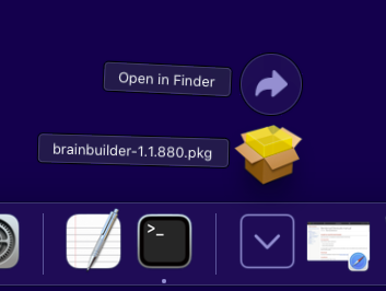
Right-click on brainbuilder-[version].pkg, and choose menu item Open with [Installer].
At this point, a warning pops up.
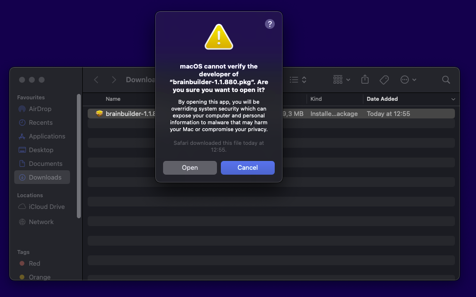
Click on [Open]
Troubleshoot windows installation
Microsoft security fixes
We have given up on attempting to satisfy all the complex and ever-changing Windows security requirements, so Windows will issue a warning when you install Bendyroad software.
Most browsers do not allow double-clicking on a downloaded file. You have to navigate to the location where downloaded files are stored, and then double-click on it.
Once you start the installer package, Windows Defender shows up with a warning.
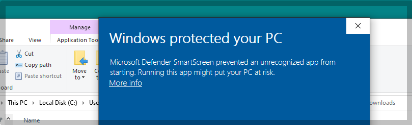
Click on [More info]. The name and version of the package are displayed as: brainbuilder-[version].msi.
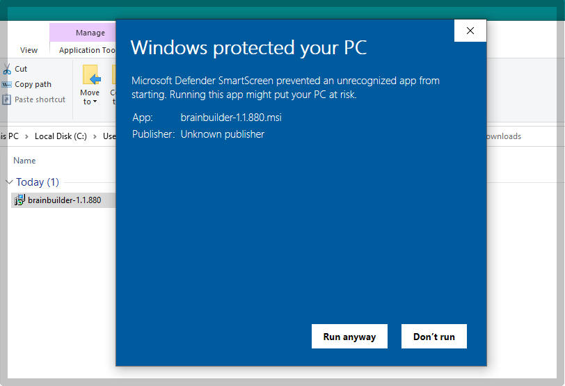
Click on [Run anyway]. The installer will start.
Types
| Type | Description | Minimum Value | Maximum Value |
|---|---|---|---|
| BIT | BIT is a 1 bit number. | 0 | 1 |
| U8 | U8 is an unsigned 8-bit integer. | 0 | 255 |
| U16 | U16 is an unsigned 16-bit integer. | 0 | 65,535 |
| U32 | U32 is an unsigned 32-bit integer. | 0 | 4,294,967,295 |
| U64 | U64 is an unsigned 64-bit integer. | 0 | 18,446,744,073,709,551,615 |
| S8 | S8 is a signed 8-bit integer. | -128 | 127 |
| S16 | S16 is a signed 16-bit integer. | -32,768 | 32,767 |
| S32 | S32 is a signed 32-bit integer. | -2,147,483,648 | 2,147,483,647 |
| S64 | S64 is a signed 64-bit integer. | -9,223,372,036,854,775,808 | 9,223,372,036,854,775,807 |
| F16 | F16 is a 16-bit floating point number. | Implementation-dependent | Implementation-dependent |
Each of these data types serves a specific purpose and can be used to optimize memory usage and computational performance in your system.
Bits
A BIT represents a binary digit, which is the smallest unit of data in a computer system. It can hold one of two values.
Integer
"Signed" means it can represent both positive and negative values.
"Unsigned" means it can only represent non-negative whole numbers.
Floating
Floating point numbers are designed to represent real numbers, allowing for a wide range of values with varying degrees of precision. The range and precision of these numbers depends on the specific implementation.
See also: The use of Floating-Point Values in Embedded Applications.